

Follow these steps to expand the functionality of your Terrain Command III with one or more Toggle Switches. The Toggle Switch is also backward-compatible with Terrain Command II units updated to firmware FW48 or higher (verify your firmware version and available updates in the Carpe Iter Controller app or NGH).
For installation of the Terrain Command Hub itself, please refer to the manual.
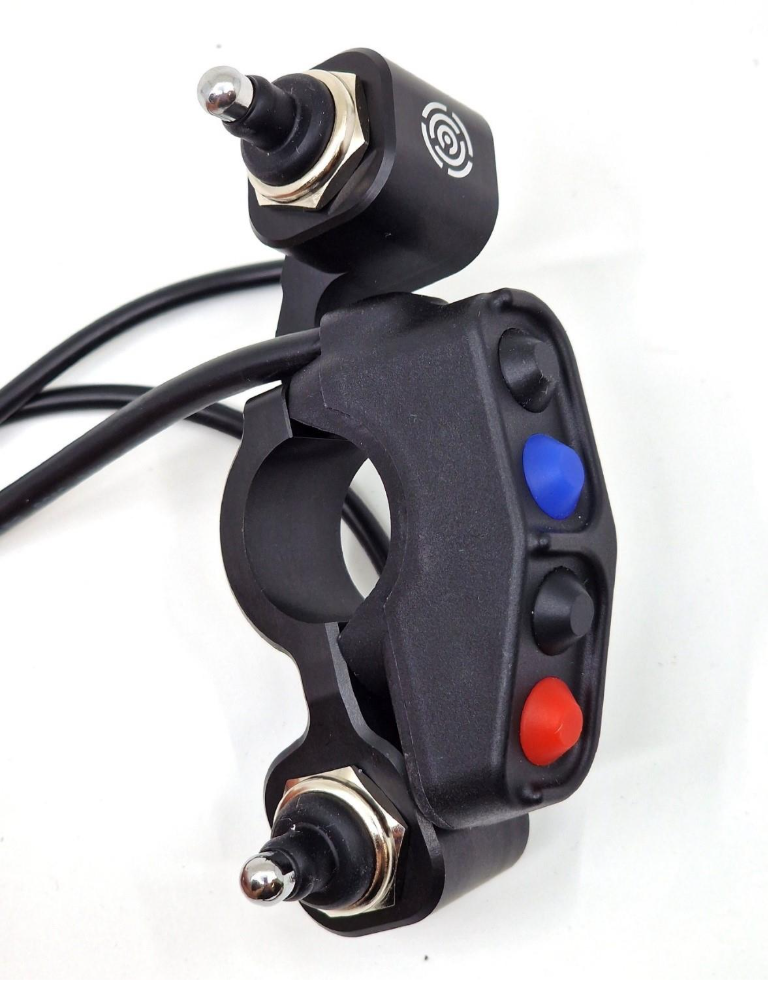
A. Assemble the Toggle Switch and Bracket
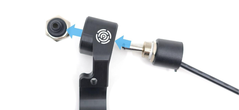
Insert the Toggle Switch into the bracket body:
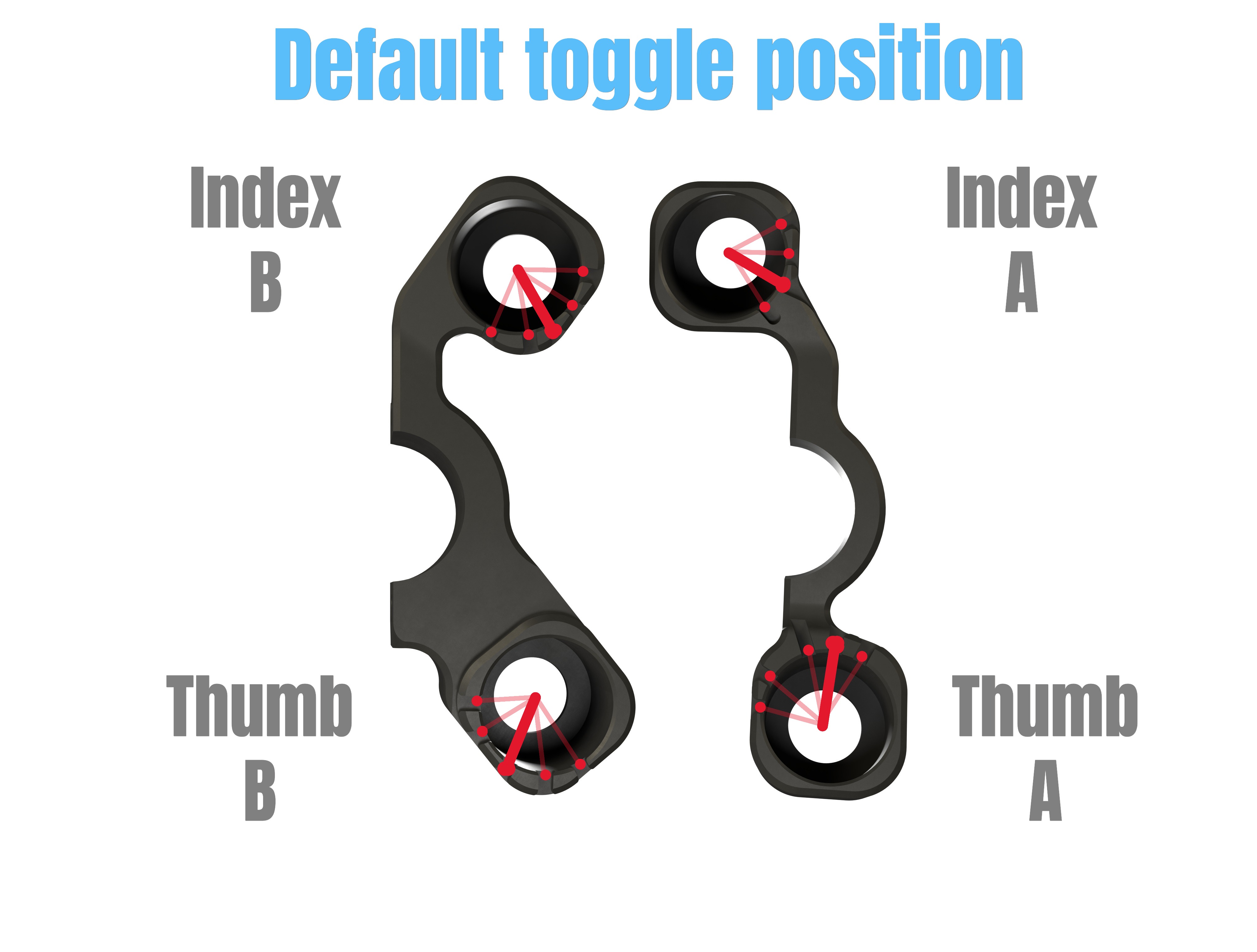
Align the alignment tabs with the locking elements on the bracket. The default position for the locking element is indicated below:
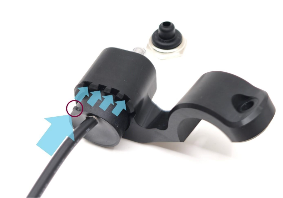
Secure the Toggle Switch by threading the cap onto the switch thread:
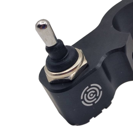
Note: Tighten lightly by hand at this stage to allow repositioning during handlebar fitting.
B. Handlebar Installation
1. Position on Handlebar
Place the Toggle Switch bracket onto the handlebar and mate it with the Terrain Command Nylon Button section:
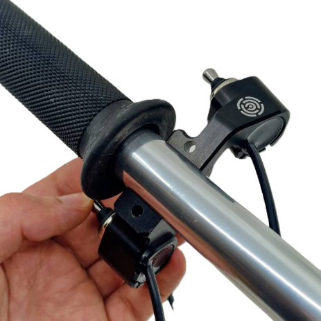
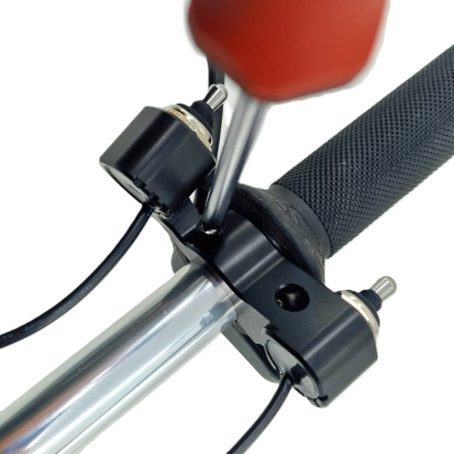
Note: Tighten the clamping screws lightly to allow angle adjustments.
2. Adjust Operating Angle & Orientation
Sit on your motorcycle in your normal riding position and adjust the angle so that both the Nylon Buttons and the Toggle Switch can be reached comfortably:
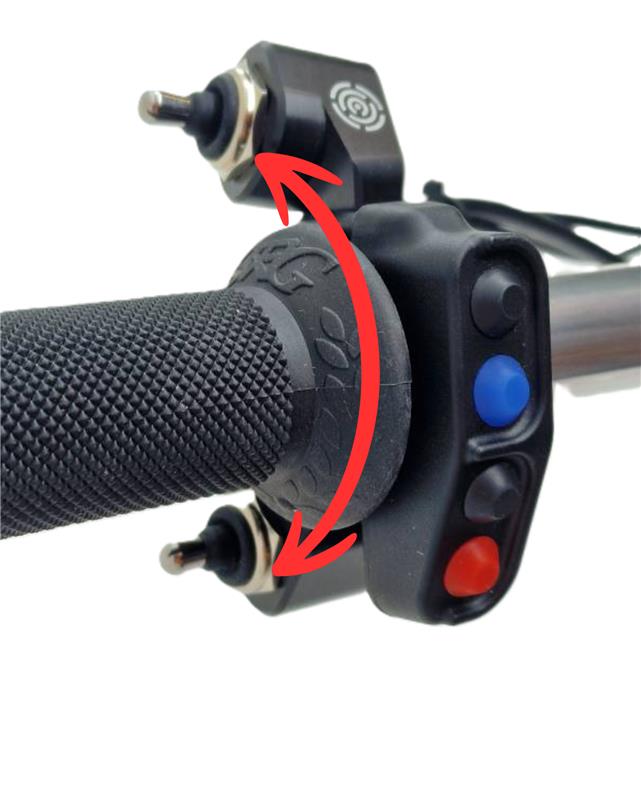
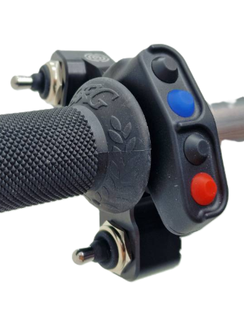
The Toggle Bracket allows orientation along two actuation axes:
- Up and down: Traditional orientation for analog rally roadbook switches.
- Back and forth: Ergonomic orientation for thumb actuation.

3. Tighten Bracket Screws
Fasten the screws securing the Toggle Switch bracket and Nylon Buttons together:
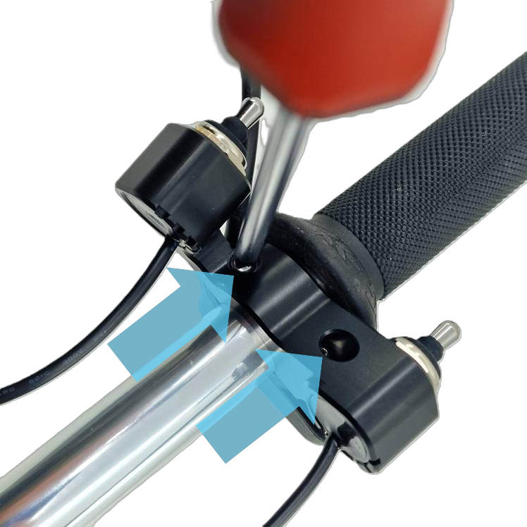
Caution: Do not exceed a torque of 0.5 Nm.
4. Tighten Toggle Switch Cap
Finalize tightening the Toggle Switch threaded retaining cap:
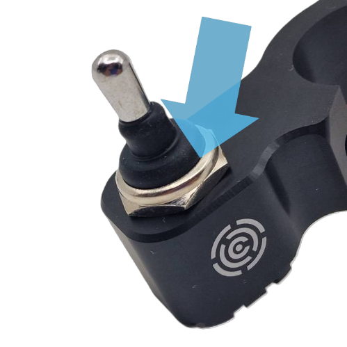
Caution: Do not exceed a torque of 0.5 Nm.
5. Cable Routing
Route all cables cleanly along the handlebar to prevent interference with the clutch lever, switchgear, or full steering lock. Fasten with zip ties, ensuring connectors comfortably reach the Terrain Command Hub before tightening.
C. Connecting to the Terrain Command Hub
When connecting, ensure correct connector indexing—mating keys and locking elements ensure proper alignment:
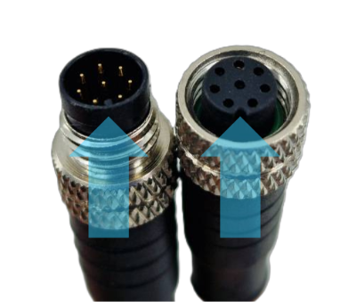
Recommendation: If the connectors will be enclosed behind motorcycle fairings, applying a mild thread-locking compound (e.g., Loctite) to the threaded collar is strongly recommended to prevent vibration-induced loosening, especially on single-cylinder motorcycles.
Configuration 1: 1x Nylon Button Section + 1x Toggle Switch
- Connect the Nylon Buttons to port BTN1 on the Terrain Command Hub.
- Connect the Toggle Switch to port BTN2 on the Terrain Command Hub.
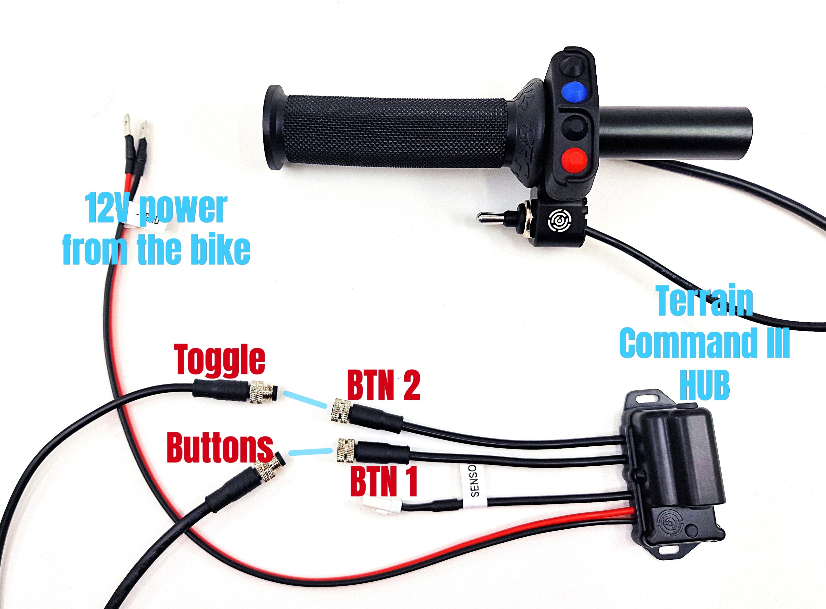
Configuration 2: 2x Toggle Switches
When installing two Toggle Switches, an Adapter for the Terrain Command is required for each Nylon Button section (1x Adapter for 1 button section, 2x Adapters for 2 button sections):
- Connect the Adapter to the BTN1 or BTN2 port on the Terrain Command Hub.
- Connect the Nylon Button section to the Adapter.
- Connect the Toggle Switch to the Adapter.
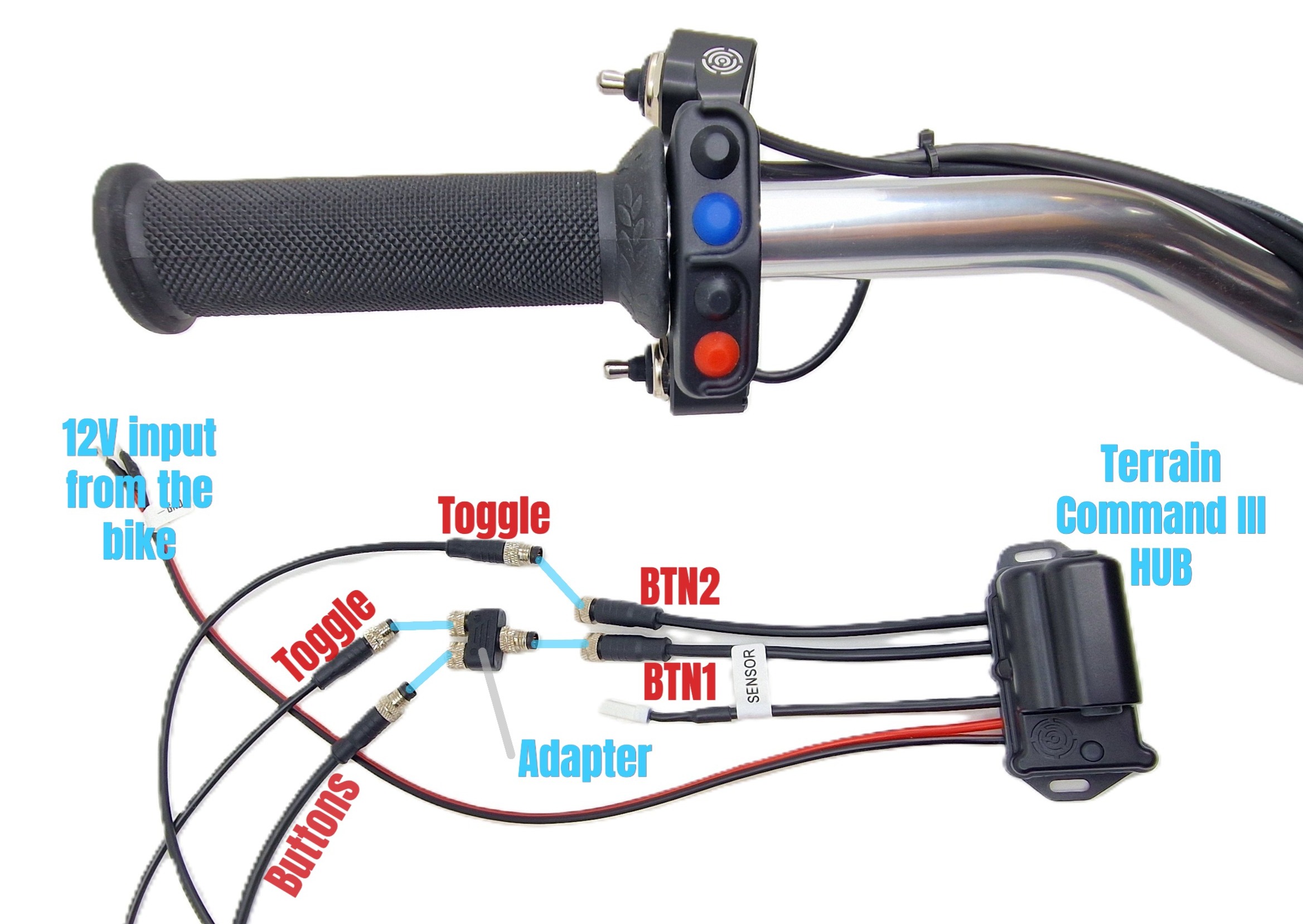
Important: Each Adapter accepts exactly 1x Nylon Button section and 1x Toggle Switch. Never connect two Button sections or two Toggle Switches to a single Adapter.
Functional Testing
Before reassembling fairings and motorcycle bodywork, verify electrical operation:
- Connect power to the Terrain Command Hub.
- Press each button and move the toggle in all directions.
- Verify that the status LED on the Terrain Command Hub changes color with each button press or toggle actuation.
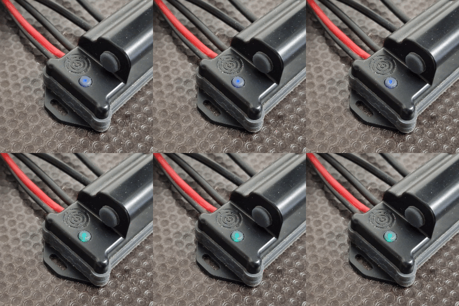
Troubleshooting: If the LED does not respond to an input, check that all connectors are fully seated with correct pin orientation and retest.
Next Steps
Once mechanical assembly and wiring verification are complete, proceed to the software setup: Toggle Switch Configuration.
Was this article helpful?
That’s Great!
Thank you for your feedback
Sorry! We couldn't be helpful
Thank you for your feedback
Feedback sent
We appreciate your effort and will try to fix the article