

Terrain Command III (TCMDC0071) User Manual
Version: 1.3
Applicable Model: TCMDC0071
1. Description
1.1. The Terrain Command III (TCMD3) is a Bluetooth Low Energy remote controller designed specifically for motorcycle handlebar mounting.
1.2. The TCMD3 system consists of the following primary components:
- 1.2.1. Button Sections: Two interchangeable button modules designed to be mounted directly on motorcycle handlebars.
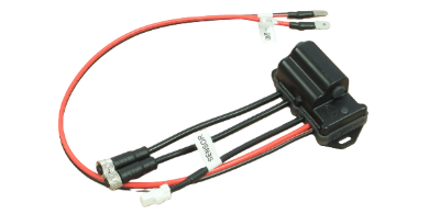
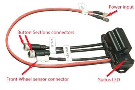
- 1.2.2. Main Hub: Houses the core control electronics and power management required for TCMD3 operation.
1.2.3. Component Overview:
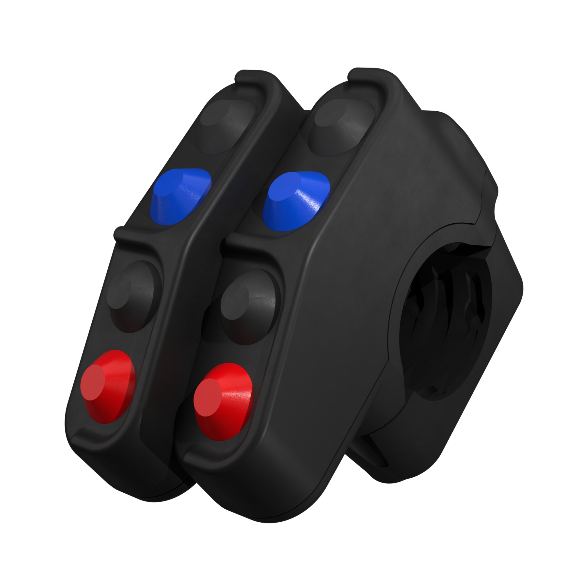
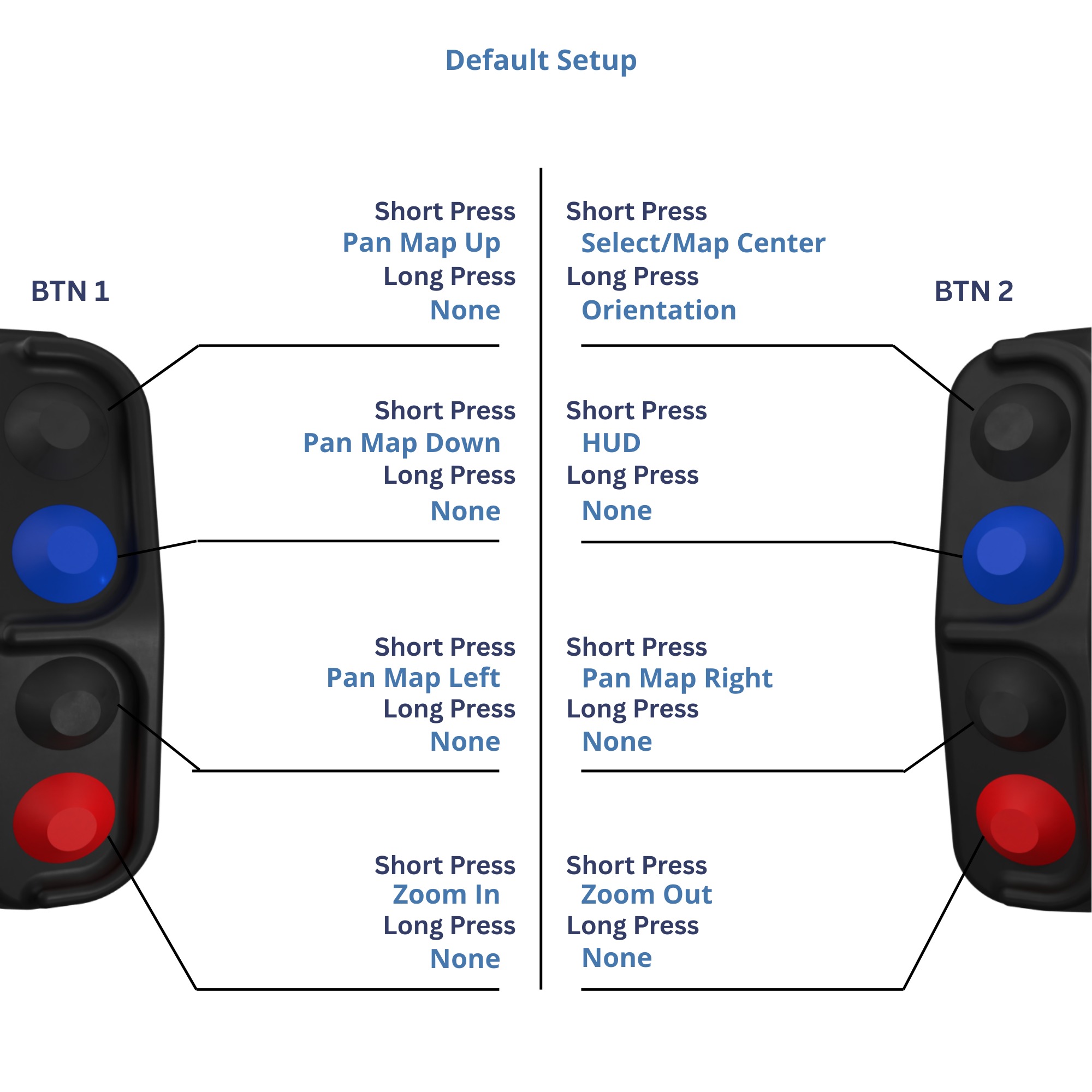
1.2.4. Button Functions:
2. Installation
2.1. Button Sections
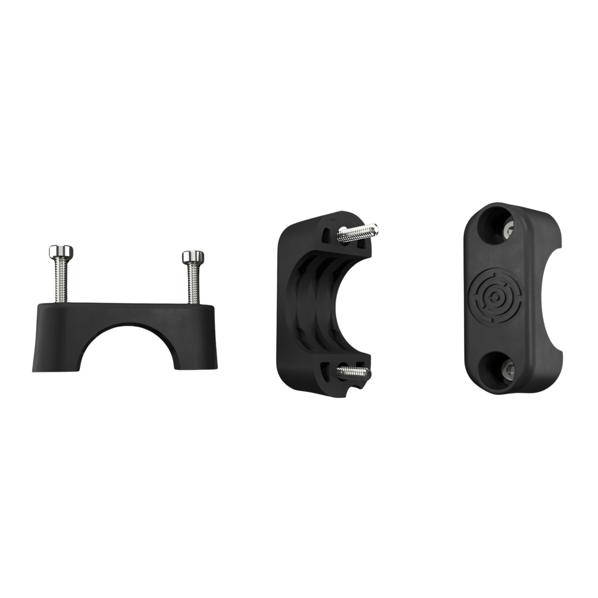
2.1.1. Button Sections are designed for permanent installation on 22 mm diameter handlebars using the provided mounting brackets and M4 screws.
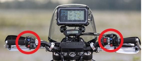
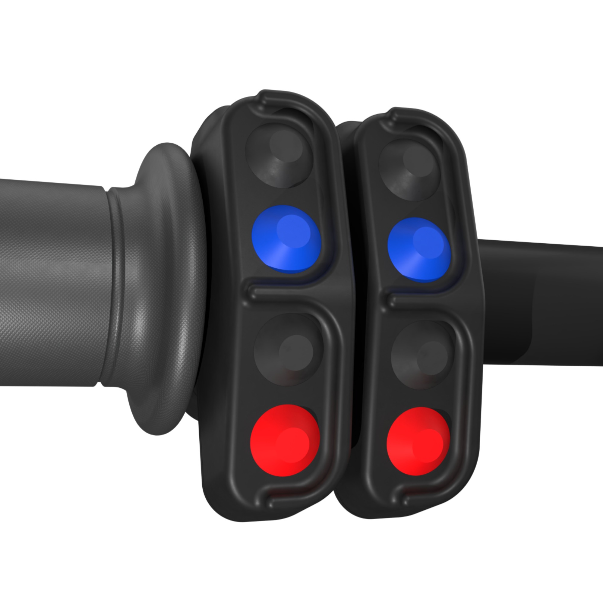
2.1.2. Mounting Configurations: The Button Sections can be mounted either on opposite sides of the handlebars or grouped side-by-side on one side.
Opposite sides:
Side-by-side:
WARNING: Mounting the Button Sections in the ideal location (between the handlebar grip and the stock switchgear) may require relocating original motorcycle control elements. Ensure all stock controls—especially brake and clutch levers, turn signals, and light switches—remain fully accessible and uninhibited.
2.1.3. Positioning: Depending on your riding posture (standing on the pegs vs. seated), rotate the Button Sections to an ergonomic angle where all controls are easily reached by your thumb.
2.1.4. Fastening: Secure the Button Sections to the handlebar using the provided brackets and M4 screws. Required tool (not included): 2.5 mm HEX key.
2.1.5. Cable Routing: Route the cables tightly along the handlebar and secure them with zip ties. Verify that neither the Button Sections nor the routed cables obstruct handlebar rotation, steering sweep, or lever travel.
2.2. Main Hub
2.2.1. Placement: Position the Main Hub behind the motorcycle fairing, ideally behind the front headlight mask.
2.2.2. Connecting Buttons: Route the Button Section cables to the Main Hub and plug them into the designated sockets. The BTN1 flag marks the Button Section intended for the left side of the handlebar (from the rider's perspective) or to the left of the other module in a side-by-side configuration.
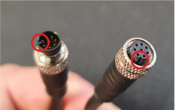
2.2.3. Connector Orientation: Observe the locking elements and guide pins to ensure proper connector alignment when mating with the Hub:
CAUTION: Tighten the threaded connector collars firmly by hand only. The threaded locking mechanism prevents disconnection from engine vibrations. Do NOT use tools or pliers to torque the connectors, as this will damage the housing.
Power Supply: Connect the Main Hub to a switched 12V auxiliary power circuit (ignition-switched) to prevent battery drain when the motorcycle is parked for extended periods.
2.2.4. Power Lead Length: The total length of the power input leads connected to the Main Hub must not exceed 2.5 m.
2.2.5. Auxiliary Power Reserve: TCMD3 features an integrated supercapacitor auxiliary power backup, sustaining standard operation for up to 30 minutes after motorcycle ignition is switched OFF.
2.2.6. Securing: Fasten the Main Hub and all wire harnesses securely to the motorcycle subframe using zip ties.
2.3. Front Wheel Sensor (Optional)
2.3.1. Purpose: If you utilize magnetic wheel-speed tracking, connect a standard 2-wire magnetic reed switch to the connector labeled SENSOR. The wheel sensor is optional and not required for standard Bluetooth controller functionality. The connection is polarity-independent.
DANGER: DO NOT connect the SENSOR port to the OEM front wheel sensor or factory motorcycle electronics. Voltage differences will permanently damage the TCMD3 Hub and motorcycle electrical systems. Other than the 12V DC and GND power terminals, TCMD3 must never interface directly with vehicle sensor buses.
2.3.2. Wiring the Adapter Cable: The SENSOR input uses a 3-pin connector. Connect standard aftermarket 2-wire reed switches using the provided 3-wire adapter cable (Red / Black / Yellow):
- Connect the reed switch leads across the Black and Yellow wires (polarity-independent).
- Leave the Red wire disconnected. Insulate and fold the unused red wire securely using heat shrink or electrical tape.
2.3.3. Connector Integrity: Do not cut off the stock proprietary connector from the SENSOR input cable; doing so voids compatibility with future Carpe Iter digital Hall-effect sensors.
3. Operation & Connectivity
3.1. Pairing: TCMD3 requires bonding via Bluetooth Low Energy with an Android host device (smartphone, tablet, or Carpe Iter Caretta). Detailed instructions are covered in the universal pairing guide: How to connect Carpe Iter remote controller.
3.2. Companion Software: Full functionality requires the Carpe Iter NGH (Next-gen HUD) application. Refer to the knowledge base for mapping and configuration: NGH support articles.
3.3. Auto-Reconnection: Once bonded, TCMD3 automatically connects to the host device whenever powered on and within Bluetooth range.
3.4. Unpairing: To completely unpair TCMD3, delete/forget the device inside your host operating system's Bluetooth settings.
3.5. LED Status Indicators
- Solid/Blinking Power LED (Hub): Indicates the TCMD3 is receiving electrical power.
- Rapid Blue Flashing: Advertising mode / ready for Bluetooth pairing.
- Slow Blue Flashing: Successfully connected via Bluetooth to a paired host device; ready for normal operation.
- Green LED (Hub): Illuminates for the duration of any button press. Useful for diagnosing connection integrity between Button Sections and the Main Hub.
4. Operating Considerations
4.1. Operating Limits: Never exceed the electrical and environmental specifications listed in Section 5.
4.2. Polarity: Always observe correct DC power polarity on input terminals.
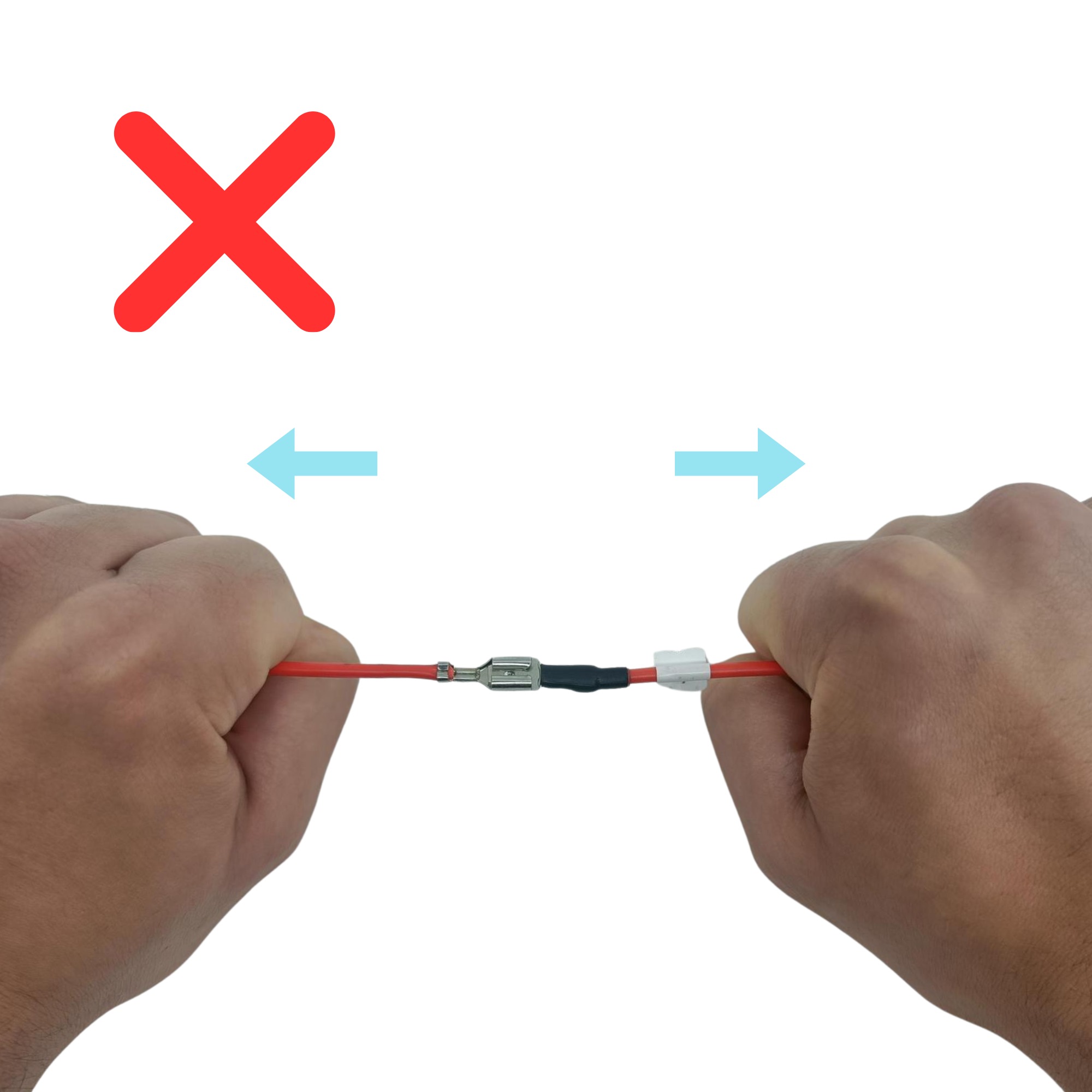
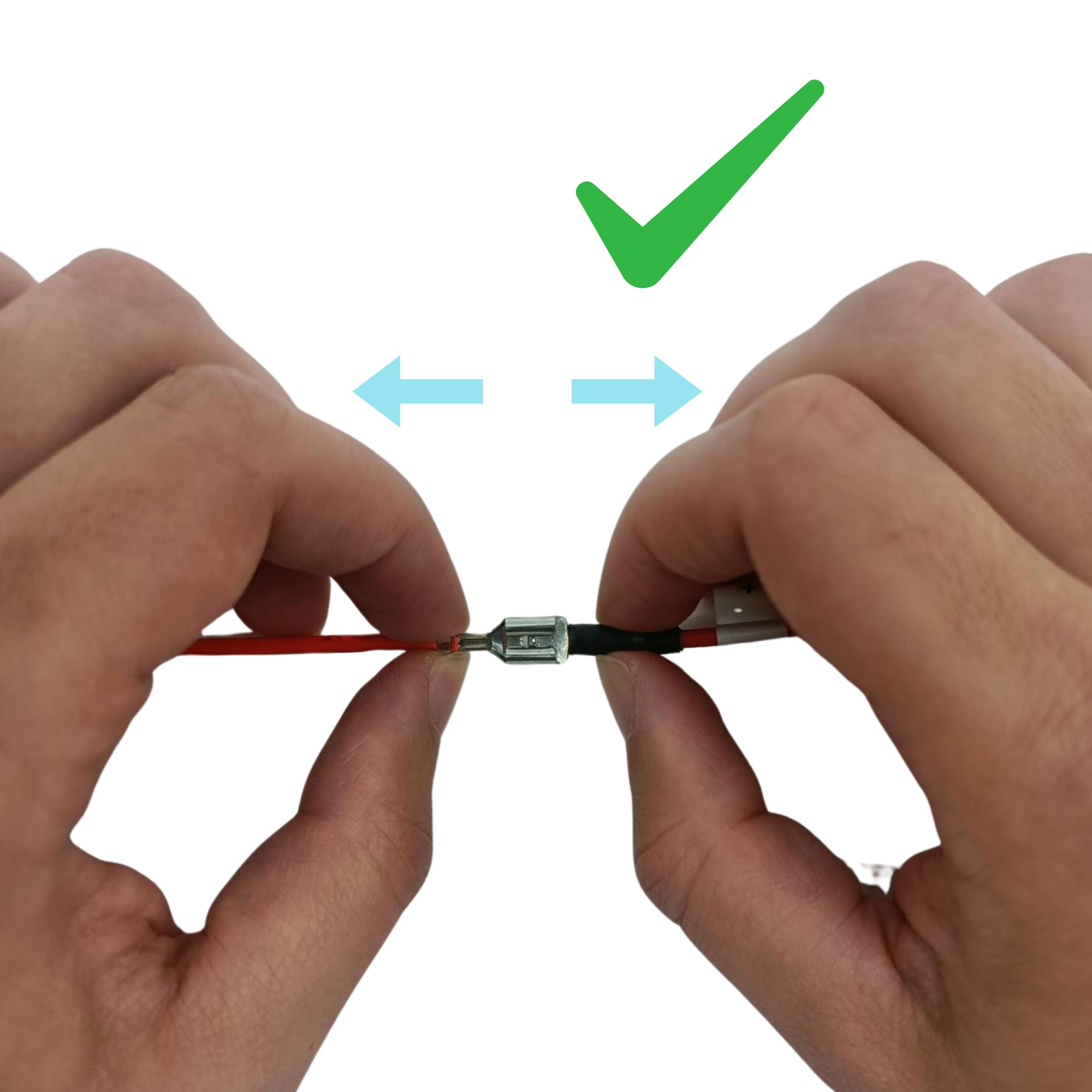
4.3. Strain Relief: Never pull on cables or wires directly.
4.4. Disconnecting Cables: Always grasp the connector bodies when disconnecting cables; never pull on the wire harness:
4.5. Thermal Protection: Exceeding the maximum operating temperature causes thermal shutdown. TCMD3 will resume operation once cooled down to rated parameters (provided excessive heat has not caused permanent component degradation).
4.6. Solar Exposure: Avoid leaving TCMD3 exposed to direct high-intensity sunlight when parked. If shade is unavailable, cover the unit to prevent extreme thermal accumulation.
4.7. Pressure Washing: DO NOT direct high-pressure water jets (pressure washers/WAP) at TCMD3 modules or button seals during motorcycle cleaning.
4.8. Button Inputs: Do not depress multiple buttons simultaneously during regular riding, as simultaneous multi-key combos can cause unpredictable input commands.
5. Technical Specifications
 Operating Voltage: 10–16V DC
- Average Power Consumption: 5 mA @ 12V (Bluetooth active, Wheel Sensor in use)
- Backup Power: Onboard supercapacitor reserve sustaining up to 30 minutes of operation when fully charged
- Environmental Rating: Weather- and dust-resistant design for demanding outdoor motorcycle use
- Operating Temperature: -15 °C to +60 °C (including solar heat accumulation)
- Storage Temperature: -15 °C to +60 °C
- Operating Humidity: 0–95% RH
- Storage Humidity: 0–70% RH
- Switches: 8x tactile mechanical pushbuttons (Nominal actuation force: 0.5 kgf; Maximum load: 2.0 kgf)
- Status Indicator: 1x RGB LED (Main Hub)
- Sensor Input: Maximum 40 Hz pulse frequency (>300 km/h on a 21" front wheel)
- Radio Connectivity:
- Bluetooth 5.0 Low Energy compliant
- Frequency Range: 2.402–2.480 GHz
- TX Power: < 10 dBm E.I.R.P.
- Modulation: Wideband
- Connectors:
- Power Input: 6.3 mm Faston male tabs
- Sensor Port: JST 03R-JWPF-VSLE waterproof connector
- Body Proximity: Not designed for body-worn operation. Maintain at least 40 cm distance between the human body and the Main Hub during operation.
- Dimensions (W x L x H):
- Button Section: 19 x 72 x 29 mm (height above handlebar)
- Main Hub: 33.6 x 55.5 x 31 mm (excluding cable exits)
6. Disclaimer
6.1. Homologation: Unless explicitly certified for a specific Carpe Iter product, no testing or road homologation has been performed for public road compliance. Use at your own risk.
6.2. Ensure equipment with edges is oriented away from the rider. Dismount unused brackets and holders when not in service.
6.3. Even when properly installed, equipment may cause injury or damage to riding apparel during falls or collisions.
6.4. User manuals and instructions are provided solely in electronic format on our official website.
6.5. Safe installation requires basic mechanical aptitude. If uncertain, have installation performed by a certified motorcycle technician.
6.6. Technical support and documentation are provided exclusively in English.
7. Warranty
7.1. Carpe Iter provides a worldwide warranty covering manufacturing defects present upon delivery: 2 years for consumer purchases and 1 year for commercial/business purchases (B2B VAT/ID registered). Warranty period commences on the date of original dispatch.
7.2. Batteries: Integrated or standalone batteries carry a limited 6-month warranty, guaranteeing at least 60% retention of nominal capacity.
7.3. Exclusions: Cosmetic wear (paint fading, discoloration, superficial corrosion not impairing function) and regular wear-and-tear are excluded.
7.4. Misuse: Warranty coverage requires strict adherence to installation manuals and operating limits. Damage resulting from improper installation or misuse is excluded.
7.5. Software: Software components and firmware are provided without warranty.
7.6. External Forces: Damage caused by external impacts (crashes, excessive pressure, abrasions, UV degradation, submersion, pressure washers) is not covered.
7.7. Consumables: Rubber seals, mounting bands, and plastic brackets are considered expendable consumables.
7.8. Claim Claims & Shipping: Defective items submitted for warranty inspection must be delivered to our designated service facility accompanied by a detailed defect report. Shipping costs, customs duties, and import taxes are the responsibility of the customer.
7.9. Remedies: Carpe Iter reserves the right to fulfill valid warranty claims via repair, replacement with an equivalent/newer model, or financial compensation.
7.10. Replacement Right: Carpe Iter may elect to replace a defective product in lieu of repair at its sole discretion.
7.11. Claim Processing: Warranty assessments will be processed within 30 days of receiving the item at our service facility.
7.12. Support Pre-Authorization: Customers must open a ticket via our official Support ticket system prior to shipping any product. Many issues can be resolved remotely without incurring shipping expenses.
Was this article helpful?
That’s Great!
Thank you for your feedback
Sorry! We couldn't be helpful
Thank you for your feedback
Feedback sent
We appreciate your effort and will try to fix the article